
Assembler(1)_1
Fig. 2.2: Program from Fig. 2.1 with Object Code

• The same program as in Fig. 2.1, with the generated object code for
each statement
– ‘Loc’ column gives the machine address (in hexadecimal) for each part of the assembled program
The program is assumed to start at address 1000
– Several functions required to translate source program -> object codes:
1) Convert mnemonic operation codes to their machine language equivalents
[e.g., translate STL to 14 (line 10)]
2) Convert symbolic operands to their equivalent machine addresses
[e.g.,translate RETADDR to 1033 (line 10)]
3) Build the machine instructions in the proper format (w/ addressing mode)
4) Convert data constants specified in the source program into their internal machine representations
[e.g., translate EOF to 454F46 (line 80)]
5) Write the object program and the assembly listing file (: 어떻게 프로그램이 번역되는지 쉽게 알 수 있음)
[e.g., Fig. 2.3 shows the object program and the assembly listing is similar to Fig.2.2]
» An assembly listing file is used for checking how the program is translated.
Fig. 2.2 (Continued)
• All of the functions above can easily be accomplished by sequential processing of the source program, one line at a time.
However, the second function for translating addresses presents a problem!
– Consider the statement <line 10> -> This instruction contains a forward reference
• Because of this, most assemblers make two passes over the source program:
– The 1st pass just scans the source program for label definitions while
assigning addresses to the labels
– The 2nd pass performs most of the actual translation previously described 16
->called two pass algorithm!
Fig. 2.3: Object Program corresponding to Fig. 2.2
• The assembler must write the generated object code into some output
devices (i.e., storage), and then this object program will later be loaded
into memory for execution
• The simple object program format used contains 3 types of records:
– Header record contains the program name, starting address, and length
– Text records contain the translated instructions and data of the program,
together with an indication of the addresses where these are to be loaded
– End record marks the end of the object program and specifies the address
in the program where execution is to begin
Three Types of Records
-? 4바이트?
• Header record
– Col. 1 H
– Col. 2-7 Program name
– Col. 8-13 Starting address of object program (hex)
– Col. 14-19 Length of object program in bytes (hex) (전체 오브젝트 코드의 len)
• Text record (several object code chunk)
– Col. 1 T
– Col. 2-7 Starting address for object code in this record (hex)
– Col. 8-9 Length of object code in this record in bytes (hex)
– Col. 10-69 Object code, represented in hex (2 columns per byte of object
code)
• End record
– Col.1 E
– Col.2-7 Address of first executable instruction in object program (hex)
• The symbol ^ is used to separate fields visually
– Of course, such symbols are not present in the actual object program
• Note that there is no object code corresponding to addresses 1033 - 2038. This storage is simply reserved by the loader for use by the
program during execution.
(이 부분은 RESW와 RESB가 있는 부분, 이 Directive들은 memory allocation을 위한 것이므로, memory allocation은 Assembler가 아닌 Loader가 하는 일이다. 따라서, Assembler에서 딱히 objecct code를 생성하지 않는다...)
The Object File for UNIX (1/2)
• The object file for UNIX systems typically contains 6 distinct pieces:
– Header, describing the size & position of the other 5 pieces of the object file (다른 파트들의 정보)
– Text Segment, containing the machine language code (번역된 머신 코드들)
– Static Data Segment, containing data allocated for the life of the program (프로그램 데이터, 변수들이 저장됨)
UNIX allows programs to use both static data (allocated throughout the program)
and dynamic data (which can grow or shrink as needed by the program)
The Object File for UNIX (2/2)
• The object file for UNIX systems typically contains 6 distinct pieces:
– Relocation Information, identifying instructions and data words that depend
on absolute addresses when the program is loaded into memory
(Loader가 allocation 할때 필요한 정보)
– Symbol Table, containing <lable – address> information about function and
global variables
(mapping table, obj 파일에 포함 X, )
– Debugging Information, containing symbolic information so that a
debugger can associate machine instructions with C source files
A concise description of how the program modules were compiled

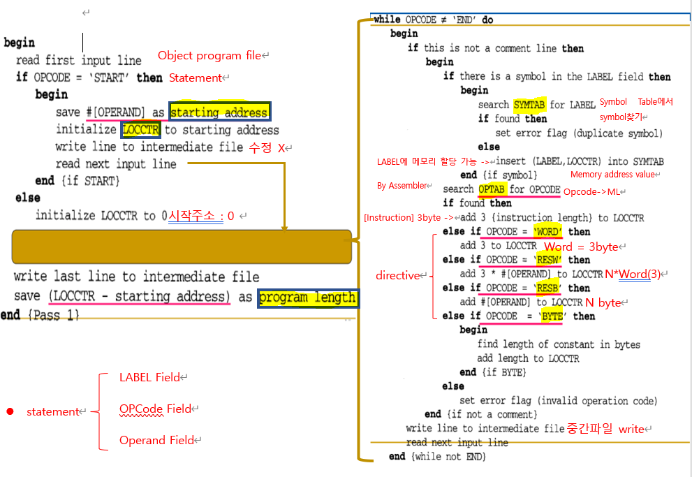
2-pass Assembler (1/2)
• Pass 1: Define symbols
: Symbol 정의 후 Symbol Table을 만드는 것이 목표
– Read a statement in a line of assembly code
– Assign an address to this statement: increasing the address by N (word
addressing or byte addressing) using LOCCTR (location counter, 다음 주소를 저장하는 전역 변수 같은 것,N은 기본적으로 byte단위)
– Save address values assigned to all labels (in symbol tables) for use in pass 2
(Assembler construct entire symbol table)
– Perform some processing of assembler directives, such as constant declaration or space reservation
(like RESW,RESB)
This includes processing that affects address assignment, such as determining
the length of data areas defined by BYTE, RESW, etc. (address assingnment에 영향을 주는 directive들)
=> Pass1 usually writes an intermediate file that contains each source (중간 파일이 만들어짐, p2에서 사용)
statement together with its assigned address, error indicators, etc.
2-pass Assembler (2/2)
• Pass 2: Assemble instructions & generate object program
– Read in a line of code: Intermediate file created in the 1st pass is used as
the input to the 2nd pass
– Translate operation code, using OP Code Table (mapping information)
– Change labels to addresses, using Symbol Table
– Perform processing of assembler directives not done during pass 1 (pass1에서 처리안된 directive 처리)
_ Produce object program
Two Data Structures of SIC Assembler (1/2)
• Operational Code Table (OPTAB)– Contain mnemonic op code and its machine language equivalent.
Also, it may contain variable-sized instruction format and length (for more complex
assemblers)
-> OP CODE와 그에 상응하는 ML을 가지고 있음.
– In Pass 1, it is used to look up and validate mnemonic codes.
– In Pass 2, used to translate the op codes to machine language.
– Usually organized as a hash table : read-only라 빠른 성능을 위해
Key: mnemonic code
Fast retrieval with a minimum of searching
Once prepared, the OPTAB is not changed.
-> 어셈블리어 (ex. LDA #5)를 어셈블러를 통해 ML로 변환.
Two Data Structures of SIC Assembler (2/2)
• Symbol Table (SYMTAB)
– Include name and value (address) for each label in the
source program, together with flags (error condition).
-> LABEL과 LABEL의 주소를 mapping한 Table

+ Also, it may contain other information such as a type or a
length.
– In Pass 1, labels are entered into SYMTAB with their
assigned addresses (from LOCCTR : location counter).
– In Pass 2, symbols used as operands are looked up in SYMBOL to obtain the addresses to be inserted in the
assembled instructions.
– Usually hash table : 효율적인 삽입을 위함
efficient insertion and retrieval are needed.
Let's study with cdoe!
- pass1 Algorithm
- pass2 Algorithm
